Thermal analysis and design software · Moats Engineering
Thermal analysis without the usual friction.
Thermal Architect is engineering software for building, solving, and understanding thermal systems, from simple resistance networks to complex electronics and fluid thermal models.
Thermal Architect is in a controlled alpha and accounts are by invitation. If you don't have one yet, ask Moats Engineering for access.
- Models
- Heat paths, circuit boards and cooling loops, in one model
- Solves
- Steady state and transient
- Studies
- Sensitivity, parameter sweeps, uncertainty, optimization
- Output
- Engineering reports, ready to share

Where it fits
Thermal analysis shouldn't require fighting the tool.
A thermal question rarely stays in one place. A junction temperature starts as a hand calculation, moves into a spreadsheet when the stack-up grows, picks up a script for the tolerance study, and finishes in a document someone retypes the numbers into.
Detailed CFD and finite-element analysis are the right tools when the geometry or the flow field is the question. A lot of design questions come earlier than that. They need a model that can be built in an afternoon and still hold up in a design review.
Thermal Architect is built for that middle ground: one model that carries the analysis, the studies and the report.
Hand calculations and spreadsheets
Fast for one path and one operating point. Harder to extend, check and hand over.
Thermal Architect
Heat paths, circuit boards and cooling loops, with established heat transfer methods built in. Studies and reports run on the same model.
3-D CFD and FEA
Resolved geometry and flow fields, for when that level of detail is what the decision depends on.
It isn't a CFD or finite-element package, and doesn't try to be. When a decision depends on detailed geometry or airflow, those tools are the right next step.
Workflow
One model, carried through the whole question.
Build it once, then keep asking it things.
-
01
Build
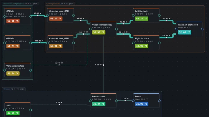
Place components on a canvas and connect them with thermal paths. Each path is described the way you would naturally specify it: a material and thickness, an interface material, a heat sink, a heat pipe.
-
02
Parameterize
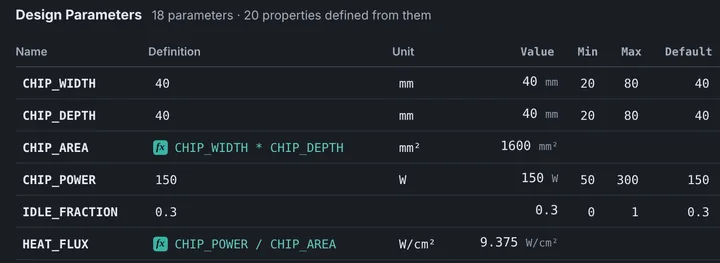
Give the important dimensions, powers and operating conditions names, then define the rest of the model from them. Change one value and everything that depends on it follows.
-
03
Solve
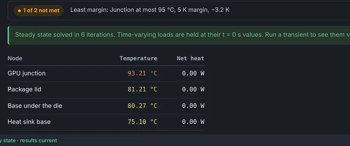
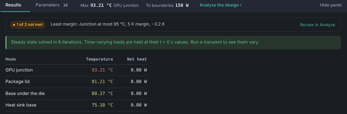
Run steady state or transient. Set requirements, such as a maximum temperature with margin, and every result tells you whether the design meets them.
-
04
Understand
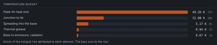
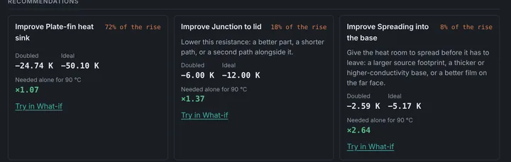
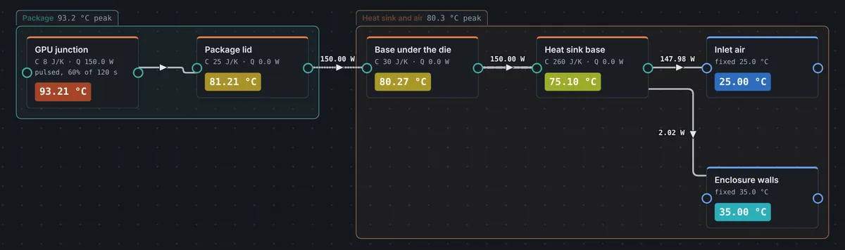
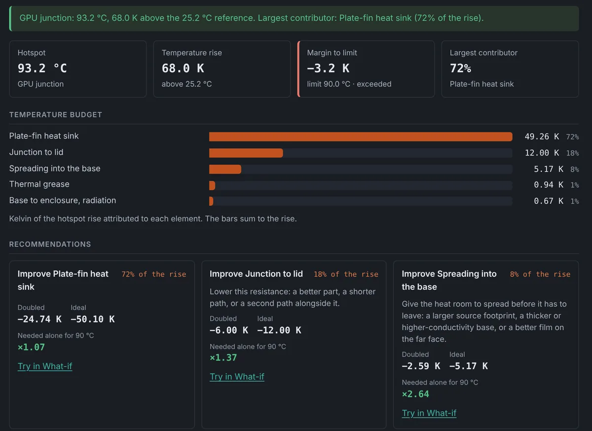
See temperatures and heat flow on the model itself, and a breakdown of which parts of the heat path account for the temperature rise.
-
05
Iterate
See which change would help most, try it, and compare. No rebuilding the model for each variation.
Capabilities
Built for real thermal engineering.
What the current release does, grouped by the job it does.
Heat transfer
- Conduction
- Natural and forced convection
- Radiation
- Contact and interface resistance
- Thermal interface materials
- Heat pipes and vapor chambers
- Heat sinks and fins
- Spreading resistance
- Boiling and condensation
Analysis
- Steady state and transient
- Temperature breakdown and recommendations
- Sensitivity ranking
- Parameter sweeps
- Uncertainty (Monte Carlo)
- What-if comparisons
- Trade-offs and optimization
- Worst-case operating conditions
- Correlation to test data
Electronics and hardware
- Circuit board thermal models
- Layout import from KiCad, Altium and IPC-2581
- Copper, vias and board construction
- Component power and junction temperatures
- Library of common component packages
- Heat sinks, interfaces and enclosures in the same model
Fluid systems
- Liquid and air cooling loops
- Pumps, fans, pipes and valves
- Cold plates and heat exchangers
- Solved together with the thermal model
- Built-in fluid properties
Engineering workflow
- Visual model building
- Named design parameters
- Requirements checked on every solve
- Material library, plus your own materials
- Reusable subsystem templates
- Saved projects
- Engineering reports
Everything listed is available in the current alpha.
In the application
From first sketch to report.
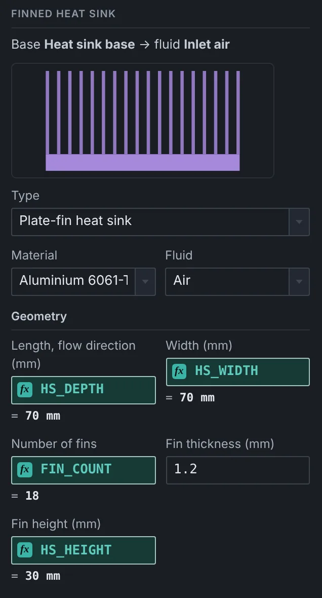
A typical electronics cooling problem, start to finish: a processor on a forced-air heat sink, with a temperature requirement to meet.
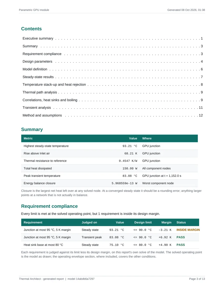
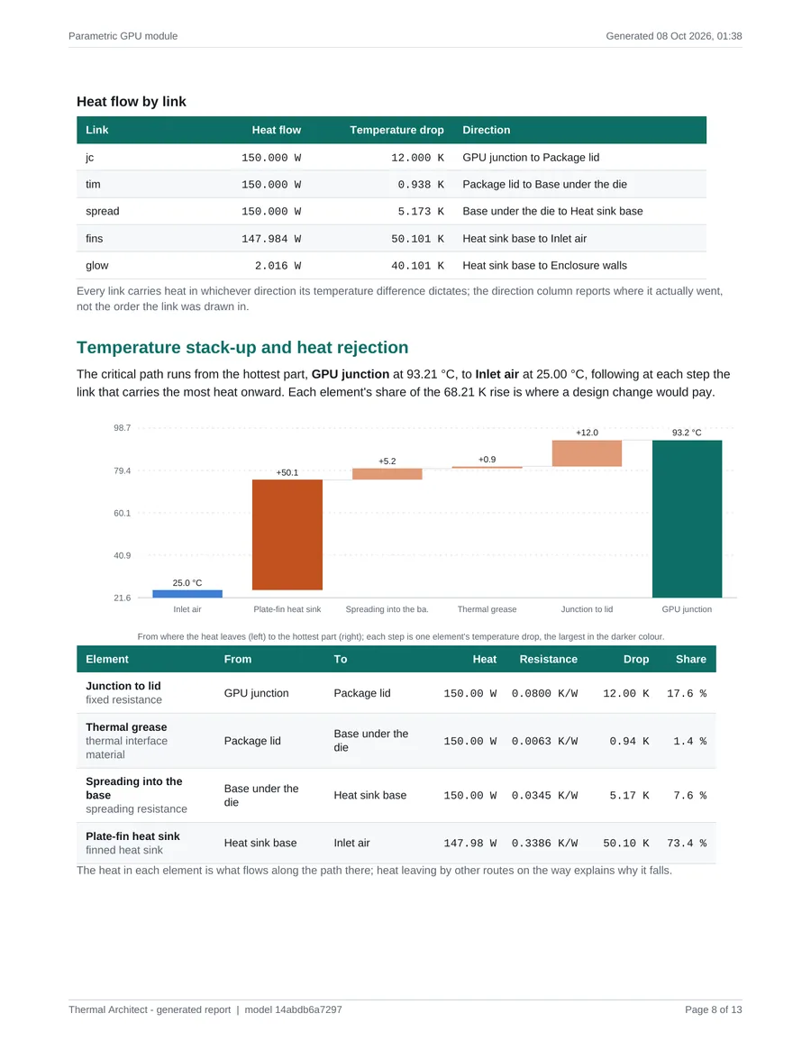
Design Parameters
Turn your model into a design space.
Dimensions, powers, material properties and operating conditions can be named once and used anywhere in the model. A heat sink's width, height and fin count become parameters, and so can the size of the chip they depend on.
Change one value and everything defined from it follows. Units are checked as you type, so mismatched quantities are caught before they reach a result.
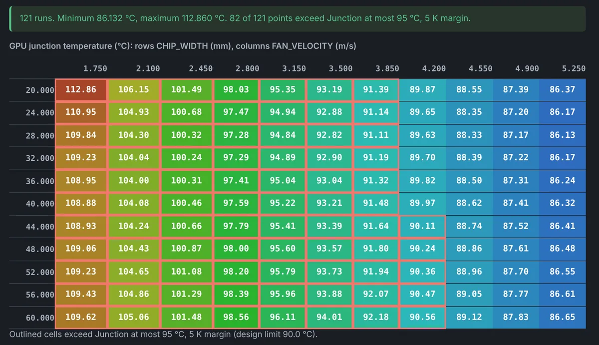
That turns “what happens if I change this?” into a quick study instead of a rebuild. Sweep one parameter, or two against each other, and every point is a full solve.
Example · parameters defined from parameters
| CHIP_WIDTH | 40 mm | |
| CHIP_DEPTH | 40 mm | |
| CHIP_AREA | = CHIP_WIDTH * CHIP_DEPTH | 1600 mm² |
| HS_OVERHANG | 15 mm | |
| HS_WIDTH | = CHIP_WIDTH + 2 * HS_OVERHANG | 70 mm |
Analysis
From a single answer to understanding the design space.
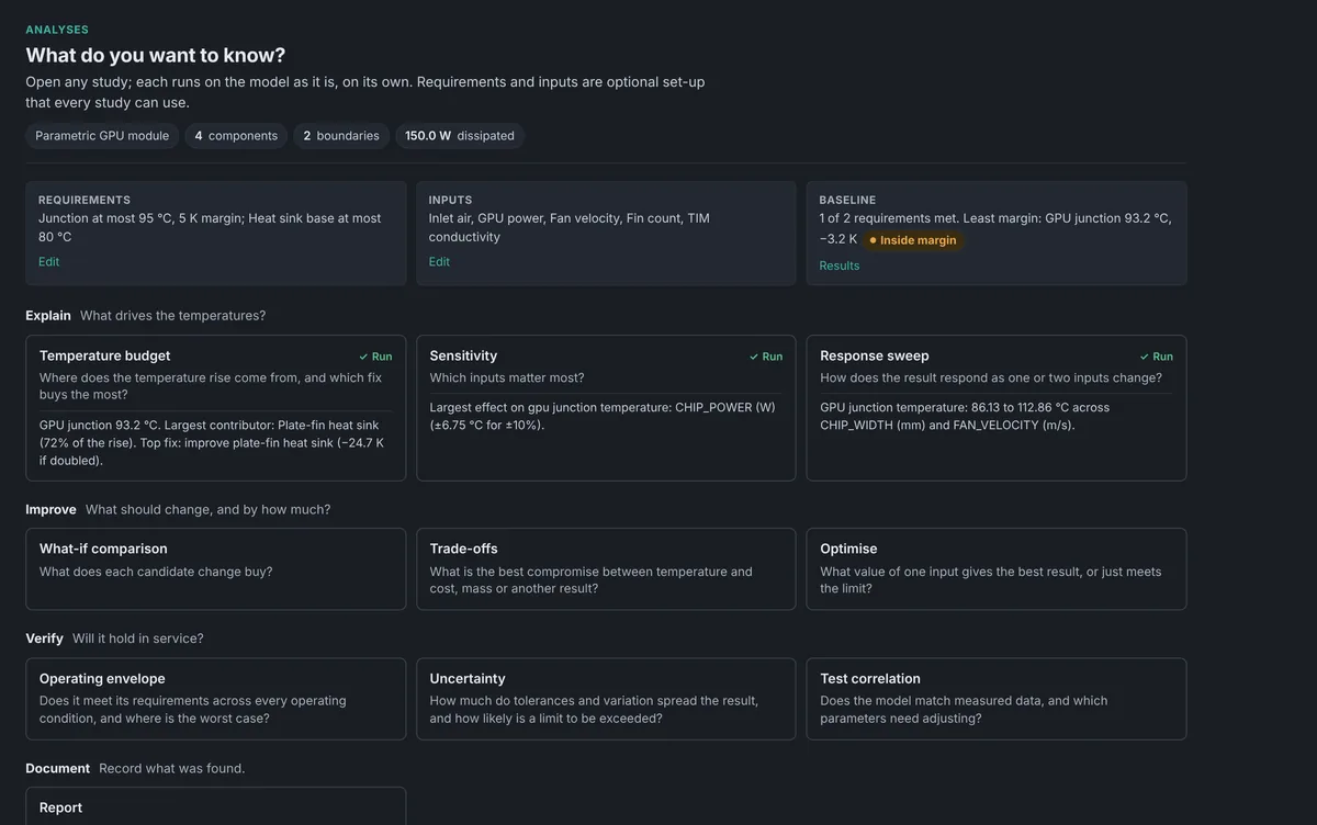
Studies run on the model you've already built, organized by the question you're asking: what drives the result, what should change, and will it hold up.
- Steady state and transient
- Operating temperatures, or how they change over time as loads cycle on and off.
- Temperature breakdown
- Which parts of the heat path account for the temperature rise, and what each possible fix would buy.
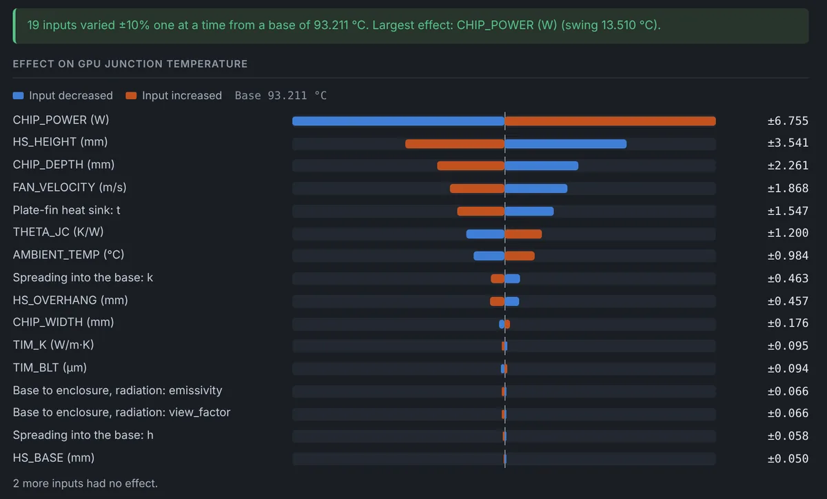
- Sensitivity and sweeps
- Which inputs matter most, and how the result responds as they change.
- Uncertainty
- How tolerances and variation spread the result, and how likely a limit is to be exceeded.
- Trade-offs and optimization
- The best balance between temperature and cost, mass or another objective.
- Worst case and test correlation
- The worst operating condition and the margin left, and tuning the model to match measured data.
Electronics
Model the electronics that actually generate the heat.
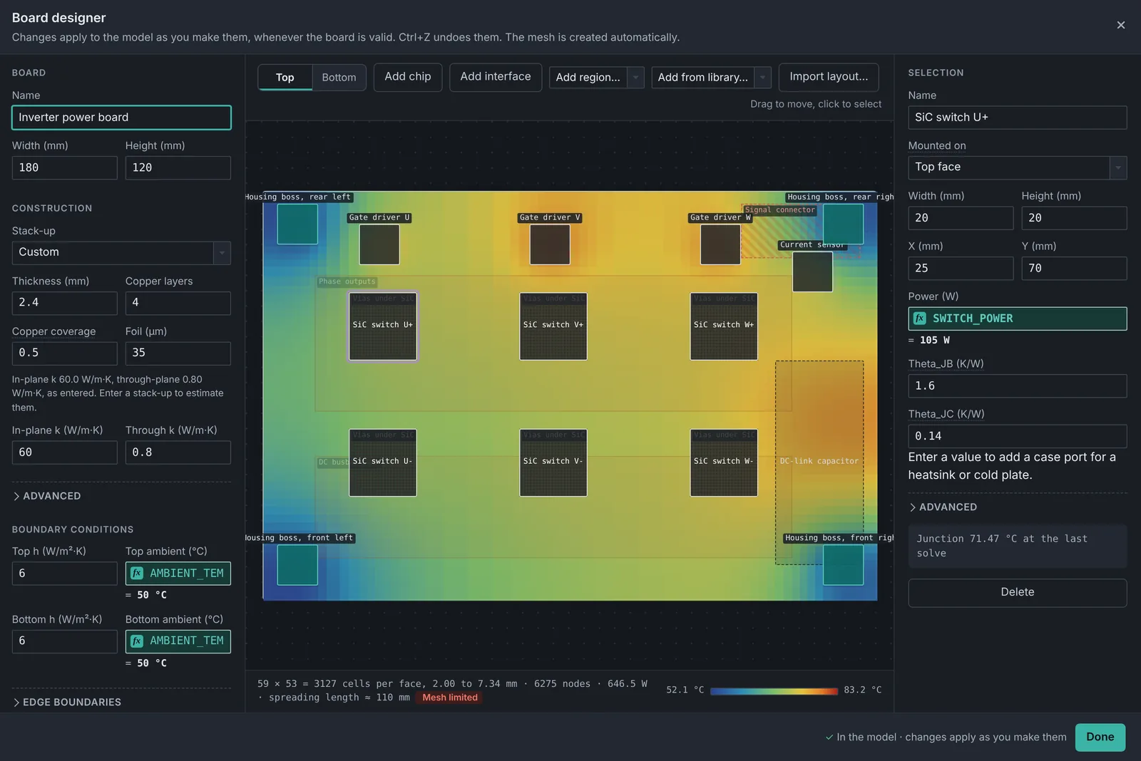
Heat spreads across a circuit board very differently from the way it moves through it, so where a part sits on the board matters. Thermal Architect models each board in detail and connects it to the heat sinks, cold plates and enclosure around it, so the board and the system are solved together.
Layouts can be imported from KiCad, Altium or IPC-2581. Anything the file doesn't contain, such as a part's power, is shown as an assumption you can review and change.
- Component placement on either side of the board
- Component power, entered directly or imported
- Board shape, layers, copper and thermal vias
- Junction temperature for every part, against its limit
- How much heat leaves through the board and how much through the package
Engineering basis
Built around engineering fundamentals.
Underneath the canvas is what an engineer would sketch on paper: a network of thermal resistances and capacitances, with energy balanced at every node. Convection, contact and two-phase heat transfer use established methods from the heat transfer literature.
The assumptions are written down. The theory manual explains how each part of a model is calculated and where the methods apply, and a separate page lists what the software does not model.
- Heat transfer
- Established, published methods, with sources cited
- Properties
- Material and fluid libraries, plus your own materials
- Time
- Steady-state and transient solutions
- Traceability
- Every report records the model and settings it came from
Who it's for
For engineers who need answers, not another workflow to manage.
Mechanical engineers
Evaluate thermal behavior during design iterations.
Thermal engineers
Build detailed thermal networks and investigate system behavior.
Electronics engineers
Understand component, PCB and enclosure thermal performance.
Hardware teams
Explore thermal design decisions before committing to detailed simulation.
Consultants
Build reusable models and communicate results clearly.
Start building your thermal model.
Explore Thermal Architect and see how quickly you can move from an engineering question to a useful answer. Ready-made examples are included to start from.
Questions it's built to answer
- How hot does this part run?
- Which part of the heat path is the bottleneck?
- What happens if the ambient rises or the fan slows?
- How much margin is left once tolerances are included?
- What goes into the design review?